How To Survive: Automotive Forum Acronyms

If you are a member of an automotive forum / message board of any sort, you are no stranger to acronyms, abbreviations, and bizarre automotive lingo.  Noob’s are often left overwhelmed and confused for weeks as they are hit with the automotive slang learning curve.  Since I too was once an automotive forum newbie, I feel like it is my duty to share some of this slang with the masses.  If you are so bold as to become a member of an automotive forum / message board, it will make your experience 10000x more fun and educational.  Here we go…….

Engine names and sizes – Could be displayed in cubic inches, liters, or factory engine code.  Engine code is typically a mix of letters and numbers.

General guidelines: Old cars = use cubic inches, newer non-performance cars = use liters, newer more performance-oriented vehicles = use factory engine codes.

Cubic Inches Examples: 289, 292, 307, 331, 348, 350, 401, 409, 429, 454, 472, 502, 572………etc….
Liters Examples: 1.8L, 2.0L, 2.2L, 2.4L, 3.0L 4.3L, 5.0L, 5.3L, 5.7L, 5.9L,  6.6L, 7.3L…..etc…..
Factory Engine Code Examples: LS1, SR20DET, 4G63, D16Y7, 13B-REW…..etc….

Transmissions – Almost always a combination of letters and numbers.

Examples: TH350, TH400, KM132, T-56, T5, C6, R-154, 4L60-E, 4T45-E

General Chat – These could be used for normal everyday terms

AFAIK – As Far As I Know
BBK – Big Brake Kit
BOV – Blow Off Valve
BRB – Be Right Back
BTDT – Been There Done That
BTW – By The Way
CAI – Cold Air Intake
CEL – Check Engine Light
DBW – Drive By Wire
DIY – Do It Yourself
FAQ – Frequently Asked Questions
FF – For Free
FS – For Sale
FTL – For The Lose
FTW – For The Win
FWIW – For What It’s Worth
GB – Group Buy
HID – High Intensity Discharge (Headlights)
HTH – Hope This Helps
IAC – Idle Air Control
IB4TL – In Before The Lock (When you know the forum moderators are going to lock the thread, you get in fast!)
IIRC – If I Recall Correctly
IMHO – In My Honest/Humble Opinion
ISC – Idle Speed Control
LMM – Losing My Mind
LOL – Laughing Out Loud
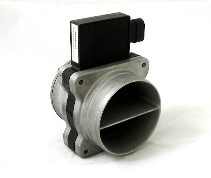
MAF – Mass Air Flow Meter
MHH – My Head Hurts
OBO – Or Best Offer
OEM – Original Equipment Manufacturer
ROFL – Rolling On Floor Laughing
TB – Throttle Body
TGFTT – Thank God For This Thread
TIA – Thanks In Advance
TTT – To The Top (Used to move your thread to the top of the page)
WOT – Wide Open Throttle
WUT/WAT/WHUT – What?!
WTB – Want To Buy
WTT – Want To Trade
YMMV – Your Mileage May Vary
YRMV – Your Results May Vary

As I come across more of these, I will add them to this list, so you can always reference it in a time of need.   Acronyms FTW!

Determining The Air Flow of an Engine

Recently I came to the conclusion that I need a bigger turbo for my truck, but since I’m cheap, I decided to commandeer a stock turbocharger from another factory built engine.   Used stock turbos are almost always the cheapest to buy because people that drive newer factory turbocharged cars upgrade them for bragging rights.  Some factory cars come with really nice turbochargers that shouldn’t be discarded as often as they are.  Newer Volkswagens, GM & Ford diesels, and Mitsubishi’s all have great turbos on them that are just asking to be mounted onto engines that they don’t belong on.  The problem is that you need to figure out which turbo is the best size for your application.  As you may guess, this is when math enters the building. The good news is that I have done most of it for you.

I created a turbo sizing spreadsheet that calculates the engine air flow with or without a turbocharger in CFM and Lbs/Min based on inputs of your choosing.  Just change the numbers in the green boxes to your own specification to display your air flow.  Once your numbers are all in there, you can compare them to any turbo compressor map.  This will help you determine the which size turbo is best for your application.

Step 1: Cubic Inches.  Type in the cubic inches of your engine into the upper green box.  In my case, I am starting with a 2.0L engine which is 122 cubic inches. If you don’t know your cubic inches, I made a conversion box for that too.  Cell H19, check it out.

Step 2: Volumetric Efficiency.  Now you need to take an educated guess at your volumetric efficiency.  In the most basic of words, this is a measurement of how efficiently your engine can move air/fuel into and out of your engine.  Unless you have a really polished high performance engine, your volumetric efficiency is probably somewhere between 75% and 90%.  I have read that most modern 4 valve engines are in the neighborhood of 85%, so that’s what I’m going with for mine.

Step 3: Boost!  This is how much pressure you expect your turbo to make when you are beating the heck out of it.  I’m going with 20 psi here as a starting point.

Step 4: Ambient Temperature is the temperature outside.  85 degrees sounds like a perfect sunny day!

Step 5: Compressor Efficiency Range.  This is found on a compressor map like this one from turboneticsinc.com. You can see that towards the bottom of each ring, there is a number in the 60’s and 70’s.  That is your compressor efficiency within that lobe of the compressor map.  You want to land above 70% when all the math is done. Throw “70” in that box as a starting point.  The more efficient your turbo is, the less  heat your turbo makes.  As the efficiency goes down, the outlet temperature of the turbo goes up.  Simple enough right?

Step 6: Intercooler Efficiency / Intercooler Pressure Drop / Air Filter Pressure Drop.  I have read the most “decent” intercoolers are around 60-65% efficient, with .5-1 PSI of pressure drop.  The average air filter has .5-1 PSI of pressure drop before the turbo.  Some high performance air filters actually list this stat, which is pretty awesome.   Naturally you want the least amount of pressure drop possible across the intercooler and air filter, with the highest efficiency intercooler.  Little changes in these areas pay huge dividends in horsepower.  Play with the numbers a bit and look how much the air flow changes.

Step 7: Engine Compression Ratio.  This is something that you will need to look up, or figure out mathematically for your engine.  It represents the ratio of the combustion chamber volume; its largest capacity to its smallest capacity. In my case 8.5 to 1.

With these inputs, you can see how the air flow changes in columns B, C, and D based on RPM (Column A).  If you have a compressor map for the potential turbocharger for your vehicle, you can determine if it will be within the turbochargers efficient range based on your engine specs.

Let’s see an example, shall we?

I am too scared to rev my engine past 7000 rpm, so why don’t we assume that 7K is my red line.  At that rpm, my max air flow is 31.53 lbs/min (426.24 CFM).  My Density Ratio (Cell K4 in the spreadsheet), is 2.03.  (Density Ratio is more accurate to use on compressor maps because it accounts for temperature.)  Cross those two points on the compressor map (seen in red), and you notice that I would actually be ~73% efficient at 7000 rpm.  This sounds like a great place to be, except that I rarely hang out at 7K rpm.  The majority of my time is spent at 2500-4500 rpm, which would put me below 70% on the compressor map.  This is hard on the turbo, and worse for performance.  So for me, this turbo is just too big!  I would need something smaller for my engine to be happy at lower rpm’s.

compressormap

Does any of that make sense? Should I try again?

MAP & IAT vs. MAF

MAP Sensors

MAP is an acronym for Manifold Absolute Pressure.  The MAP sensor is a key component in a Speed Density fuel injection system, and measures pressure and absence of pressure (vacuum) at the intake manifold.  MAP sensors typically have 3 wires: a 5 volt reference signal wire, a ground wire, and the wire that goes back to the ECU for all that sweet, sweet air related data.  The ECU (a.k.a PCM, ECM) then calculates the air / fuel ratio based on VE tables within the computer. We will cover Volumetric Efficiency tables at a later date.  Just imagine a magical grid in the computer that says “if you see this voltage from the MAP, then do this…”.  The cool thing about these sensors is that they are simple, and can be easily used for higher performance applications.   The bad thing about these sensors is that they are part of the speed density fuel injection system that doesn’t know exact amounts of air going into the engine, it just makes educated guesses at it.   These guesses are all well and good, but solid numbers are always better.  Or are they?  Naturally, there is much more to a speed density fuel injection system than just a MAP sensor…..

IAT Sensors

IAT is an acronym for Intake Air Temperature.  The IAT sensor measures the air temperature that is going into your intake manifold.  The colder the air, the more dense it is, and the more fuel you need to keep your engine happy.  Coool ….literally.  Almost all IAT’s are simple two wire devices that measure resistance.  As the air temperature changes, the resistance in the sensor changes and the ECU knows to change the A/F ratio based on this.  Combine this data with that of the MAP sensor and your computer can now give a pretty accurate guess of the volume of air moving through your engine.  This is great news, but it’s all based on calculations, instead of real solid numbers.  This is where speed density is tossed aside and big Mr. MAF enters the party…..

MAF Sensors

MAF is an acronym for Mass Air Flow.  These sensors are pretty impressive because they measure air volume, along with temperature, all in one (no IAT necessary!).  Remember, the MAP sensor above measured intake manifold pressure / vacuum and then estimated air volume with computer software.  A MAF actually measures real air volume so that the computer doesn’t need to guess what it might be.  As you can imagine, MAF’s are typically more accurate ways of measuring the amount of air that goes into your engine.  This sounds great, right? Well…. it is, on a stock vehicle, and even lightly modified ones.  However, if you decide that you want to make way more horsepower than your car was ever intended for (where do I sign?), then MAF just isn’t going to cut it.  MAF’s quickly become bottlenecks in your air intake system because they can only measure “X” air at once.  If your engine needs more than “X” amount of air, then your MAF freaks out causing your engine to run lean and quickly turns rotating engine parts into liquid hot magma, (Hellooo magma).  This is where Speed Density is welcomed back into the party, and brings along a couple of lovely friends, known as MAP and IAT.

So as you can see, there are pros and cons to each, and it really depends on your vehicle and its modifications to choose who is the cooler sensor at the engine party.  Luckily, choosing one or the other only needs to happen when you modify your car to the extreme.  If you have a stock car, none of this really even matters.

For those of you that are attempting to make crazy horsepower,  what do you guys & gals prefer?

L92 Heads: Do you know how awesome they are?

Can you believe that brand new from GM this bare cylinder head was only slightly over $200? Over the weekend, I spent a fair amount of time staring at a 6.2L L92 engine out of a Cadillac Escalade, along with all of it’s wonderful aluminum parts.  It made me want to build one for myself really badly.  The weight savings, the easy power, the plentiful parts.  There is no downside to this?! At $200 per bare head, you could build a complete set of these awesome flowing, 70cc combustion chamber, aluminum cylinder heads for like $800 (maybe cheaper if you are savvy).  These L92 heads, when combined with the right intake manifold, will allow you to effortlessly make 500+ hp without any power adders.  Just bolt it together and enjoy your tire smoke. After years of dealing with cast iron SBC and BBC cylinder heads, blocks, and intake manifolds, I don’t think I can go back.  I feel obligated to grab new technology by the horns and do a dance with it.  Who’s with me on this?

Your Car Tires Are How Old??

Did you know that your car’s tires have the week and year that they were made stamped right into the side of them?  Pretty cool right?  On the side of every tire made after the year 2000, there is an oval with 4 digits in it (as pictured above).  The first two digits are the week of the year, and the second two digits are the year itself.  On this 2005 Mazda Rx8 tire, you can see “1009”, which means it was built during the 10th week of 2009.  Not too shabby.

Now, if your tires were made before the year 2000, things were a little more wild and crazy.  They still told you the week and the year that they were built, but they did it with three digits instead of four. (What?!)  Tire manufactures assumed that nobody would have tires more than 10 years, so the numbers could potentially repeat themselves once each decade.  Let’s have an example, shall we?  Pretend you have a super rare, silver 1992 Dodge Spirit R/T 2.2L Turbo.  It’s all original right down to the tires, and with over 220 horsepower on tap, you are looking to burn the meats off in grand fashion before replacing them with M/T ET Drag Radials.  Dangit! You’re shoelace is untied again.  You bend down and catch a quick glance of the oval on the tire with “211” stamped into it.  You’re a clever cat, so you obviously know that the first two digits mean that the tire was made during the 21st week, and the “1” is the 1st year of that decade, which was 1991.  You quickly lace up your high-tops, hop in the Spirit, pop your MC Hammer tape in, rip the e-brake, and proceed to shmammer the tires as your friends cheer you on in fits of joy.

…annnnnd back to reality for a quick moment – This tire dating knowledge is not just a great way to impress the ladies, but it is a good piece of info to have when buying new (or used) tires.  Naturally you want the latest and greatest rubber between you and the asphalt.  Whether you can see it or not, old tires just don’t grip like a new set does.