The manifold absolute pressure (MAP) sensor measures the air pressure in the intake manifold for the computer to adjust the air/fuel ratio. When a MAP sensor fails, it can affect engine performance or turn on the check engine light for code P0107B. This article explains how to test a MAP sensor with an advanced scan tool and a multimeter or voltmeter if you suspect the sensor is defective.
Lack of Power and Poor Fuel Economy Are a Couple Symptoms of a Bad MAP Sensor
How to Test the MAP Sensor with a Scan Tool
How to Diagnose the MAP Sensor with a Scanner
- Check the Sitting MAP Sensor Reading
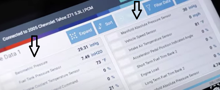
Turn the vehicle on without starting and with an advanced scan tool check the MAP sensor reading. Some vehicles have a barometric pressure sensor, which is the same type of sensor. It measures the barometric pressure in the air, and this reading will change with the altitude. The two readings should be equal or about the same.
- Check the Working MAP Sensor Reading
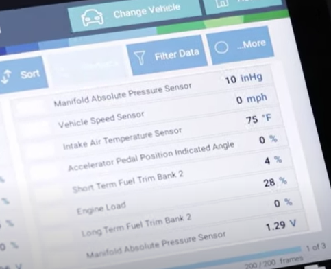
Start the vehicle and see if the MAP sensor takes a reading and changes when you press the throttle. It should rise quickly when the gas is pressed, fall to a low number when the gas is released, and stabilize at a higher reading shortly after.
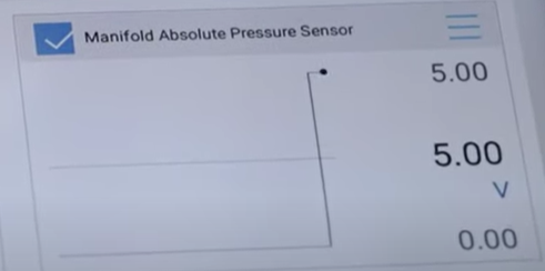
- Graph the MAP Sensor Reading
Graph the sensor with an advanced scan tool. If the are spikes in the reading like in the picture below, the sensor is working intermittently and needs to be replaced.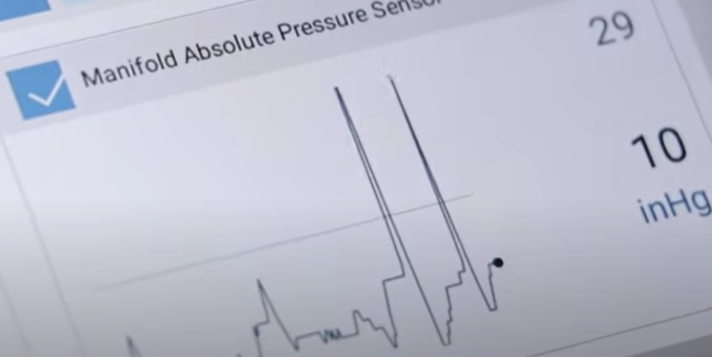
- Replace the Bad MAP Sensor
A bad MAP sensor will draw a low reading compared to the barometric pressure sensor reading and will have an inaccurate or no reading with the vehicle on. If this happens, the MAP sensor needs a replacement
Free Shipping on Auto Parts with No Minimum

How to Test the MAP Sensor with a Multimeter or Voltmeter
The MAP sensor is usually attached to the air intake.
Steps for Testing the MAP Sensor Electrical Connector
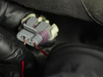
- Disconnect the electrical connector
- Look for corrosion in the connector’s terminals
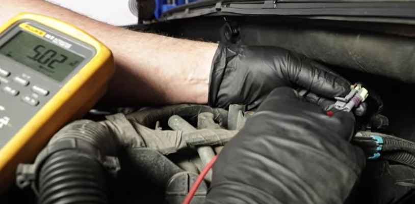
- Test the connector with a voltmeter
- Place a lead on the electrical ground and lightly probe the outside terminal for 5 volts
- Place a lead on the ground terminal (the opposing outside terminal) and test the outside terminal for 5 volts to confirm the computer is grounding properly
How to Test the MAP Sensor Electrical Connector with a Jumper Harness and Scan Tool
Step 1. Make a Jumper Harness with a Fuse
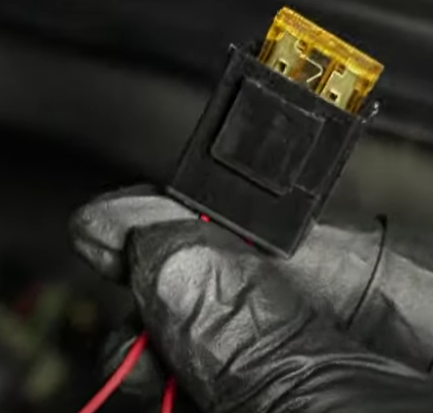
Make a jumper harness with a fuse and spliced wire ends.
Step 2. Place the Spliced Wire Ends to the Electrical Connector’s Terminal and Read for 5 Volts
Lightly press the spliced ends to the outside terminal (5 volts) and the center terminal.
Confirm with a scan tool that the connector is sending 5 volts down the signal wire.
If the terminal is getting electricity like in the exercise above, the MAP sensor is faulty and needs to be replaced.
Replace the MAP Sensor Yourself
Replacing the MAP sensor is usually a simple repair a novice can do. If you have tested the MAP sensor and know it’s defective, replace it yourself with videos at 1aauto.com
Shop Parts Featured in This Article
Related Content
- How to Test a MAF Sensor
- What is a MAP Sensor & What does a MAP Sensor do?
- MAP vs. MAF vs. IAT Sensors
- How to Use a Car Tester
- Does your Engine Have a Knocking Sound?
- How to Use a Digital Multimeter
- How to Test a Fuse with a Multimeter